
DESCRIPTION AND MAINTENANCE
Proper weapons maintenance is important, so it is a vital part of all gunnery training programs. Good maintenance contributes to weapon effectiveness as well as to unit readiness. This chapter provides a technical description of the M203 grenade launcher, its components, and its ammunition. It also discusses proper procedures for clearing, disassembling, cleaning and lubricating, inspecting, and caring for the weapon.
The M203 grenade launcher is a lightweight, single-shot, breech-loaded, pump action (sliding barrel), shoulder-fired weapon attached to either an M16A1 or an M16A2 rifle (Figure 3-1).

The technical data for the M203 grenade launcher is as follows:
a. Weapon.Length of rifle and grenade launcher (overall)..9.0 cm (39 inches) Length of barrel only...........................30.5 cm (12 inches) Length of rifling...............................25.4 cm (10 inches)
Weight of launcher unloaded.....................1.4 kg (3.0 pounds) Weight of launcher loaded.......................1.6 kg (3.5 pounds) Weight of rifle and grenade launcher with both fully loaded........................5.0 kg (11.0 pounds)
Number of lands.................................6
b. Ammunition.
Caliber.........................................40 mm Weight..........................................227 grams (8 ounces) (approximately)
c. Operational Characteristics.
Action..........................................Single shot Sights: Front.........................................Sight post Rear..........................................Leaf Chamber pressure................................206,325 kilopascals (35,000 psi)
Muzzle velocity.................................76 mps (250 fps)
Maximum range...................................400 meters (1,312 feet) (approximately)
Maximum effective range: Fire-team sized area target...................350 meters (1,148 feet) Vehicle or weapon point target................150 meters (492 feet)
Minimum safe firing range (HE): Training......................................165 meters (541 feet) Combat........................................31 meters (102 feet)
Minimum arming range............................14 to 38 meters (46 to 125 feet) (approximately)
Rate of fire....................................5 to 7 rounds per minute
Minimum combat load.............................36 HE rounds
| WARNING |
|---|
WHEN FIRING CLOSE-IN, SUCH AS IN URBAN AREAS, TRENCHES, AND OTHER RESTRICTIVE TERRAIN, OBSERVE THE MINIMUM ARMING RANGE TO ENSURE THE ROUND CLEARS OTHER FRIENDLY FORCES. |
The major components of the M203 grenade launcher and their purposes are discussed here and are shown in Figure 3-2. The sight assemblies, the trigger and trigger guard, and the safety are shown in Figures 3-3 through 3-8.
a. Handguard. The handguard assembly houses the rifle barrel (Figure 3-2).

b. Quadrant Sight Assembly. The quadrant sight assembly, which attaches to the left side of the rifle's carrying handle, enables the grenadier to adjust for elevation and windage (Figure 3-2). This assembly consists of a mounting screw, the sight, sight latch, rear sight aperture, sight aperture arm, front sight post, and sight post arm (Figure 3-3).
(2) Sight arm and range quadrant. The sight arm mounts both the sight aperture arm (which holds the rear sight aperture) and the sight post arm (which holds the front sight post). This allows the sight to pivot on the range quadrant to the desired range setting. The range quadrant is graduated in 25-meter increments from 50 to 400 meters. Applying rearward pressure on the sight latch releases the quadrant sight arm so it can move along the range quadrant. The desired range number is then centered in the rear sight aperture. Releasing the sight latch locks the sight in position.

(b) To move the impact of the projectile 5 meters at a range of 200 meters, turn the elevation adjustment screw one full turn.
(4) Rear sight aperture. The rear sight aperture is on the sight aperture arm, which is attached to the rear portion of the quadrant sight arm. Use the rear sight aperture to make minor adjustments in deflection (windage) when zeroing the launcher as follows:
(b) To move the impact of the projectile 1 1/2 meters at a range of 200 meters, move the rear sight aperture one notch.
c. Receiver Assembly. The receiver assembly houses the firing mechanism and ejection system and supports the barrel assembly (Figure 3-2).
d. Barrel Assembly. The barrel assembly holds the cartridges ready for firing and directs the projectile (Figure 3-2).
e. Leaf Sight Assembly. The leaf sight assembly is attached to the top of the handguard (Figure 3-4). The leaf sight assembly consists of the sight, its base and mount, an elevation adjustment screw, and a windage adjustment screw. Elevation and windage scales are marked on the mount. The folding, adjustable, open ladder design of the sight permits rapid firing without sight manipulation. The front sight post of the M16-series rifle serves as the front aiming post for the M203 leaf sight.

(2) Sight mount and sight. The grenadier uses the sight mount, which is attached to the sight base, to raise or lower the sight. Though the range is not marked on the sight in meters, the sight is graduated in 50-meter increments from 50 to 200 meters, which are marked with a "1" at 100 meters and a "2" at 200 meters.
(3) Elevation adjustment screw and elevation scale. The screw attaches the sight to its mount. When the screw is loosened, the sight can be moved up or down to make minor adjustments in elevation during the zeroing procedure. The rim of a 40-mm cartridge case is useful for turning the screw. Raising the sight increases the range, lowering the sight decreases the range. The elevation scale consists of five lines spaced equally on the sight. The index line is to the left of the sight. Moving the sight one increment moves the impact of the projectile 10 meters in elevation at a range of 200 meters.
(4) Windage screw and windage scale. To make minor deflection adjustments during the zeroing procedure, a knob on the left end of the windage screw is turned. The scale has a zero line in its center and two lines spaced equally on each side of the zero line. Moving the knob one increment on the windage scale moves the impact of the projectile 1 1/2 meters at a range of 200 meters.
| DANGER |
|---|
THE 50-METER MARK ON THE LEAF SIGHT BLADE IS MARKED IN RED TO EMPHASIZE THAT THIS RANGE MUST NOT BE USED FOR ZEROING PROCEDURES. ZEROING IS EXTREMELY DANGEROUS AT 50 METERS OR LESS DUE TO FRAGMENTATION. |
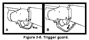
f. Trigger Guard. The trigger guard protects the trigger (A, Figure 3-5). Depressing the rear portion of the trigger guard rotates it down and away from the magazine well of the rifle, which allows the weapon to be fired while the firer is wearing gloves or mittens (B, Figure 3-5).
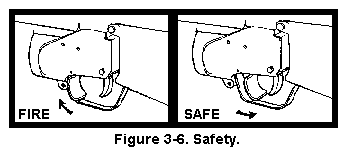
g. Safety. The safety is inside the trigger guard, just in front of the trigger. For the launcher to fire, the safety must be forward. When the safety is rearward, the launcher is on SAFE. The safety is manually adjusted, (Figure 3-6).
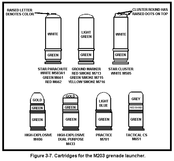
The M203 grenade launcher uses several fixed-type, low-velocity 40-mm rounds. The M203 fires high-explosive, illuminating, signaling, CS, and training ammunition. This paragraph discusses only the most commonly used ammunition.
| WARNING |
|---|
IF FIRED INTO SNOW, 40-MM ROUNDS MAY NOT HIT HARD ENOUGH TO DETONATE. IF AN UNDETONATED ROUND IS STEPPED ON OR DRIVEN OVER, IT MAY EXPLODE. DURING TRAINING, AVOID THIS HAZARD BY FIRING ONLY TP ROUNDS IN THE SNOW. |
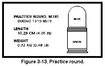
a. Types, Characteristics, and Capabilities. All M203 grenade launcher rounds are fixed rounds (Figure 3-7). (TM 43-0001-28 provides more details).



b. Storage. Ammunition should be stored under cover. If this is not possible, it must be stored at least 15 centimeters (6 inches) above the ground and covered with a double layer of tarpaulins. These should be placed so they protect the ammunition, allowing for ventilation. Trenches must be dug to prevent water from flowing under the ammunition.
c. Care, Handling, and Preservation. Ammunition containers should not be opened until ammunition is to be used. Ammunition removed from the airtight containers is likely to corrode, particularly in damp climates. Soldiers must take the following precautions:
(2) Avoid exposing ammunition to the direct rays of the sun. Hot powder can cause excessive pressure when the round is fired.
(3) Do not lubricate ammunition. This can cause dust and other abrasives to collect on it and damage the operating parts of the weapon.
d. Packaging. Ammunition is packaged in boxes according to the type of ammunition.
(2) Smoke and cluster ammunition. Each wire-bound box of smoke and cluster ammunition contains 2 cans with 22 rounds each, for a total of 44 rounds.
(3) CS ammunition. Each box of CS ammunition contains 2 cans with 4 bandoleers of 6 rounds each, for a total of 48 rounds.
The soldier must clear the weapon before performing maintenance on it. FM 23-9 provides instructions for clearing the M16-series rifles. To clear the grenade launcher--
a. Push in the release button, and pull the barrel forward.
b. Watch to see if a round extracts.
c. Place the safety on SAFE.
d. Inspect the breech to ensure a round is not present.
e. Pull the barrel to the rear until it clicks. This cocks the weapon.
f. Place the safety on FIRE.
When disassembling the weapon, the soldier places each part, as it is removed, on a clean, flat surface such as a table, shelter half, or disassembly mat. This simplifies the task of keeping up with the parts and aids in reassembly. The soldier will later assemble the grenade launcher in the reverse order that he disassembled it. (Only ordnance personnel disassemble the grenade launcher beyond the steps described here.) To disassemble the weapon--
a. Loosen the mounting screw and remove the quadrant sight assembly from the carrying handle of the M16-series rifle (Figure 3-15).

b. Remove the barrel assembly and handguard assembly, in either order.
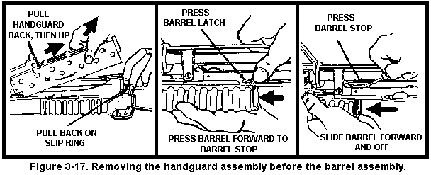
(2) Handguard assembly first. Pull back on the M16's slip ring and remove the handguard by pulling it up and back. Push the barrel latch and move the barrel forward until it hits the barrel stop. Use a cleaning rod to depress the barrel stop, and slide the barrel forward and off (Figure 3-17).

After firing the grenade launcher, or if it has been idle for a long time, the soldier must clean and lubricate it as follows:
a. Bore. Attach a clean, dry rag to the thong, and thoroughly moisten the rag with CLP. Pull the rag through the bore several times. Attach the bore brush to the thong, pull it through the bore several times, and follow this with more rags moistened with CLP (Figure 3-18). Pull dry rags through the bore, and inspect each rag as it is removed. The bore is clean when a dry rag is removed unfouled. Pull a rag lightly moistened with CLP through the bore to leave a light coat of lubricant inside the barrel.
b. Breech Insert. Clean the face of the breech insert with a patch and CLP. Remove this CLP with dry rags, then lubricate the breech with a new, light coat of CLP.
c. Other Parts. Use a brush and dry rags to clean all the other parts and surfaces. After cleaning, apply a light coat of CLP to the outside of the launcher.

d. Safety Mechanism. Clean the safety mechanism properly with CLP, then lubricate it with CLP.
e. Special Lubrication Requirements. Lubricate the grenade launcher only with CLP and IAW the following environmental guidelines:
(2) Damp or salty air. Clean the weapon and apply CLP, grade 2, frequently.
(3) Sandy or dusty air. Clean the weapon and apply CLP, grade 2, frequently. Remove excess CLP with a rag after each application.
(4) Temperatures below freezing. When the weapon is brought in from a cold area to a warm area, keep it wrapped in a parka or blanket, and allow it to gradually reach room temperature. If condensation forms on the weapon, dry and lubricate it at room temperature with CLP, grade 2, before returning it to cold weather. Otherwise, ice will form inside the mechanism.
3-8. INSPECTION
Inspection begins with the weapon already disassembled into its major groups
or assemblies. Parts with shiny surfaces are serviceable. The following parts
of the weapon and related equipment are inspected as described, IAW
TM 9-1010-221-10:
a. All parts--wear and damage, including burrs, scratches, and nicks.
b. Handguard--cracks, dents, or distortion that prevents its firm attachment to the rifle.
c. Leaf sight assembly--bent or damaged parts, rust or corrosion, and legibility of markings.
d. Barrel--cracks or dents.
e. Cartridge and retainers--breakage, bends, chips, or missing parts.
The soldier assembles the grenade launcher in the reverse order of disassembly.
a. Install the barrel by pressing the barrel stop and sliding the barrel into the receiver (Figure 3-19).

b. Lock the barrel by moving it rearward until it closes with a click (Figure 3-20).

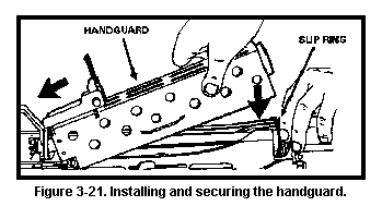
c. Install the handguard, and secure it with the slip ring (Figure 3-21).
d. Install the quadrant sight assembly (Figure 3-22).

e. Perform a function check in the correct order to ensure that the grenade launcher has been assembled correctly. Notify the unit armorer at once if the launcher fails to function. Conduct the function check as follows:
| WARNING |
|---|
IF THE SEAR MALFUNCTIONS, THE LAUNCHER COULD |
(3) Check the leaf sight assembly windage adjustment screw for proper operation. Move the elevation adjustment screw only if the weapon has been zeroed.
(4) Move the barrel forward and back, to be sure both the stop and barrel latch function.
Certain steps must be taken before, during, and after firing to properly maintain the grenade launcher.
a. Before firing--
b. During firing--
3-11. CARE AND HANDLING UNDER NBC CONDITIONS
If contamination is anticipated, the soldier should apply cleaner, lubricant, preservative (CLP) to all outer metal surfaces of the weapon. Ammunition should never be lubricated. The soldier should keep the weapon covered as much as possible. If the weapon is contaminated, he should decontaminate it IAW FM 3-3 and FM 3-4, then clean and lubricate it.