|
|
|
|
|
|
|
|
|
|
|
|
Reprinted from The International Arms Review
The
SG 510 (also known as the AM 55 and StGw
57) Is provided with a geared-up, de layed
blowback locking system that utilizes twin
bolthead pivoting cylinders, along the lines
of the rollers used In the German G3 and
the Spanish CETME. The transmission ratio
is 1:4. This weapon is designed for mass
production, so the emphasis lies on pressed
sheet-metal components. It delivers both
semi-automatic and full-automatic fire. The
large sidelever can be rotated to S (safe),
E (semiautomatic) or M (full-automatic). The SG 510 always fires from a closed
bolt.
Ammunition is fed vertically into the breech
from a 24-cartridge magazine. The spent
cases are ejected to the right, at a right
angle to the receiver. Grenades can be
launched without adding a special provision. The Integral muzzle brake reduces
recoil by about 25 per cent. Both the front square
blade sight, laterally adjustable, and the
peep receiver sight fold down when not in
use. A hinged carrying handle is located at
the balance point, at the front of the receiver. For safety's sake a floating
pin indicates whether or not a cartridge is in the firing chamber.
The handguard and buttstock are of
acid-proof rubber. The buttstock can be propped
against a hard surface when the rifle
is firing grenades. The SG 510 can be field
stripped quickly without tools. No pro vision
has been made for a riflescope as the
Swiss army makes use of a special sniper's
rifle equipped with a stronger muzzle brake and a bipod. Here reference is being
made
to a short-stocked, heavy barrelled repeater
that is fitted with the K 31 action.
 |
(Left) AM55 Prototype. |
 |
7.5
mm Swiss Ammunition The Swiss themselves call these cartridges "Modell 11 ", and six specials exist alongside the standard rifle round. 1 . Tracer with a 765 yard trail. Colour code: case head, red. 2. Light armour piercer, steel cored. Colour code: case head, violet. 3. Light armour piercer / tracer. Colour code: case head, red primer, violet. 4. Proof-house load. Colour code: case head, black case, coppered. 5. Grenade cartridge 44. For launching grenade 58. 6. Blank load. Used on manoeuvres. Plastic cased. |

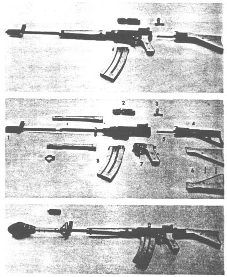
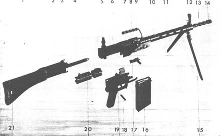
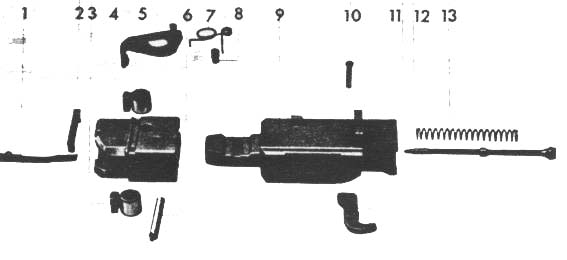
| Main
Component
Parts of SG 510
1 Rubber buttstock 2 Rear receiver compartment 3 Clasp lugs 4 Recoil spring / damper 5 Peep sight 6 Receiver proper 7 Carrying handle 8 Breechring 9 Removable caps for locking recesses 10 Spring clip 11 Barrel cowling 12 Front sight 13 Forward end of barrel designed as cup discharger 14 Muzzle brake 15 Bipod 16 Magazine 17 Charging handle 18 Crossbolt for trigger unit 19 Pistol grip with trigger unit 20 Bolt assembly 21 Passageway for sling |
 |
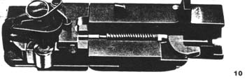
| Parts
Legend forIllustration
10 Bolt Assembly 1 Extractor 2 Cylinder check 3 Cylinders 4 Bolthead 5 Ejector 6 Cotter 7 Ejector spring 8 Retainer 9 Boltbody 10 Firing-lever pin 11 Firing lever 12 Firing pin 13 Firing-pin spring |
 |
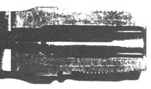 |
| Cutaway of firing chamber |
1.
Receiver
This
consists of three sections: the centre housing (6), the breechring (8), which
is welded to (6), and the rear compartment (2). Element (2) is bayonet locked
to the centre housing or receiver proper (6) by means of clasp lugs (3). The
buttstock (1) is also secured to the rear compartment (2). The latter accommodates
the recoil spring and special dampers (4), whereas the receiver proper (6) guides
the bolt assembly (20). Ejection port and guide slot for the charging handle
(17) are right of the receiver. The peep sight (5) is mounted on the roof of
(6). The forged breechring (8) contains the recesses, sealed outwardly by removable
metal caps, into which the locking cylinders of the bolt assembly (20) engage.
Element (8) is also the base for the hinged carrying handle (7), the screw-in,
barrel (13) and the cartridge indicator pin.
A ventilated cowling or casing (11) extends as far as the front sight (12) and
bayonet lug. The collapsible bipod (15) can be moved up and down the barrel
cowling (11), and locked in position by a sprung clip (10). The right leg of
the bipod (15) has a graduated scale for the rainbow (high-angle) trajectory
described by a rifle grenade when ignited by a standard grenade cartridge, whereas
the left leg is graduated for a grenade which is launched with a booster load.
The barrel cowling (11) is bridged to the breechring (8). The handguard wraps around the lower section of this junction.
The muzzle serves as a muzzle brake (14) and grenade launcher, where by the
bulbous section of the barrel supports the grenade. A spring clip mounted in
the bulb nearest the front sight prevents a grenade from slipping off the muzzle
if the rifle were inadvertently pointed downwards.
The longitudinal flutes in the firing chamber permits some gas to flow around the cartridge case, for balancing internal pressure. Furthermore, the case cannot stick to the wall of the chamber. However, in order to avert a massive escape of gas, these flutes stop about 13 mm (.512 in.) before the face of the chamber. For uniform cycling, the main force of the gas must slam the cartridge case against the bolthead, not by-pass the case.
This consists of the bolthead (4) with locking cylinders (3), cylinder check (2), ejector and spring (5), and extractor (1). The bolthead is pinned to the wedge-like protrusion of the boltbody (9), but can slide to and fro over a short distance. The boltbody contains the firing pin (12) with spring (13), plus the firing lever (11). The bolt assembly can be dismantled without tools.
This consists of two long coil springs that are telescoped into each other (4). This unit is anchored in the buttstock.
This is grouped in the trigger housing (19). The housing itself is hooked
into the receiver (6) and held by a crossbolt (18).
The trigger housing contains the pistol grip, safety lever, magazine cutoff,
and swing-out winter trigger guard. The pistol grip is hollow to accept the
night sight.
The letters E (semi-automatic) and S (safe) are stamped on to the receiver (6),
whereas the letter M (full-automatic) is stamped on the trigger housing (19).
|
 |
A component in the trigger housing (19) can be installed in two different ways. When white is showing, the SG 5 10 will fire single shots only.
When black is showing, full-automatic fire is possible. After military training, Swiss citizens keep their guns (and other service equipment) at home, and practise marksmanship at civilian ranges. It is at these local ranges that white must show ...Irrespective of whether the SG 510 is set at semi- or fullautomatic fire, the trigger remains two-stage. Trigger pull is also adjustable.
Note: If the bolt assembly does not return to its forward (battery) position that is, the cylinders do not engage inrecesses in the breechring, the firing pin, housed in the boltbody, lacks sufficient reach to ignite a cartridge.
 |
|
|
 |
|
| Front
Sight 21 Blade 80 Night sight filled withphosporescent substance 81 Hood 82 Post |
 |
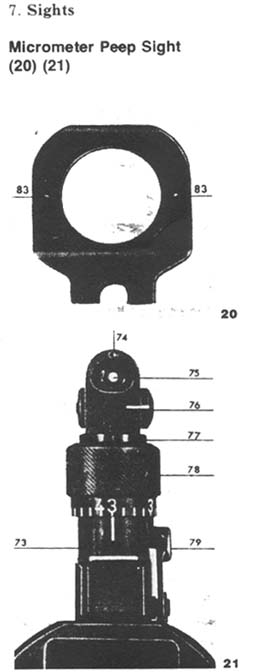
Both front sight (12) and rear micrometer peep sight (5) are folded down when not required. The hooded front sight is mounted in a T-groove on an upright post, and is adjustable for windage. For night operations the hole (80) at the apex of the hood (8 1), filled with phosphorescent substance, is aligned with a special insert that is placed in the peep sight. This sight is graduated from 110 to 700 yards. Each division of adjustment corresponds to 0.26% of the range, and change in point of impact (vertically) reads as follows:
approx. 1.2 in. at 110 yardsThe figure 3 appears twice on the scale, in red and white. Division marks and numbers in white are used when aligning tip of front sight with centre of bullseye. The red 3 allows a sixo'clock-hold (that is: front sight aligned with bottom of bullseye) at 300 metres (330 yards).
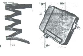
This (16) is made of sheet metal and is designed for 24 cartridges. The inspection holes in the sideplate allows cartridges to be counted. Loading is accomplished without a filler. A white magazine charged with six type-44 cartridges (Fig. 23) is used when launching grenades. Normal live rounds cannot be loaded into these white magazines. A slide on the magazine and a groove in the boltbody (20) prevent grenade cartridges being chambered automatically.
| 90
Follower 91 Front lug 92 Magazine 93 Rear lug 94 Button 95 Spring |
 |
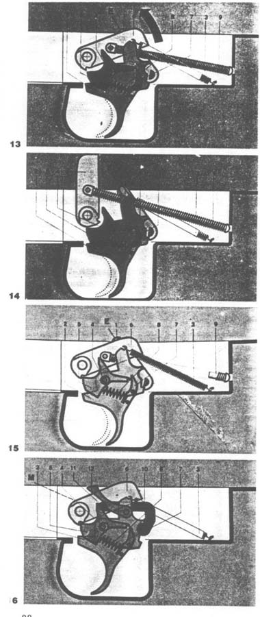
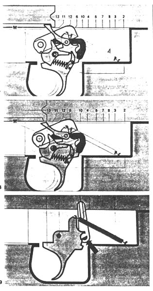
9. Operation (illus. 24-27)

Assuming the SG 510 has been readied to fire, with safety off, the operation is as follows:
By pulling the trigger, the hammer (14) is freed from the sear (5). The hammer (14) is catapulted against the firing lever (11), through thrust pressure generated by the mainspring (9). The firing lever (11) in turn impacts the firing pin, igniting the cartridge in the chamber. Gas pressure forces the brass cartridge case firmly against the walls of the firing chamber, slowing up extraction in older guns. For this reason, the SG 510 has its firing chamber fitted with longitudinal flutes, to allow some gas to flow around the outside of the cartridge case, thus tending to equalize internal pressure. Gas drives the bullet down the barrel, but also presses the spent case against the boltface, in the other direction. As seen in Fig. 24, at the moment of firing the two cylinders (3) are engaged in the recesses of the breechring (8), and are kept there by the force of the recoil spring (4) which bears against the bolt assembly (20).
At a specific pressure level, when the bullet has left the muzzle, the cylinders cave inwards and by doing so strike against the wedgelike protrusion of the boltbody (9). The boltbody thus suddenly accelerates to the rear, and when the link is taut, that is, as soon as the slack between boltbody (9) and bolthead (4) has been taken up, the bolthead is trailed along behind. This scheme accords an initial slow-motion opening of the breech, yet momentum builds up rapidly once the boltbody gets under way. During this opening phase, the heavy boltbody re-cocks the hammer (6); and the ejector (5), as it runs over a slope built into the receiver wall, flips out the empty cartridge case. This is clearly illustrated in Figs. 2 6 and 27. The compressed recoil spring and the damper unit in the buttstock brake the reward movement of the bolt assembly and then drives the assembly forward again, stripping the top cartridge from the magazine and chambering it. During this closing phase, the boltbody, which in a sense is now the trailing member, comes up behind the bolthead and cams the pivoted cylinders outward into engagement with the recesses in the breechring. The gun is ready to f ire.
A difficult problem in this type of actions is to prevent the bolt assembly jarring against the face of the firing chamber. Picture how a hammer smartly rebounds when it strikes an anvil! As this phenomenon causes stoppages, weights and claws, etc. have been incorporated into bolt systems as a counter-measure. However, the SG 510 solved this problem by giving the firing chamber a peculiar shape. Its diameter narrows just before the shoulder (Fig. 9), which means that the cartridge sticks out of the mouth of the chamber, and buffers the blow of the returning bolt assembly. This cushioning cuts bolt chatter down to a minimum.
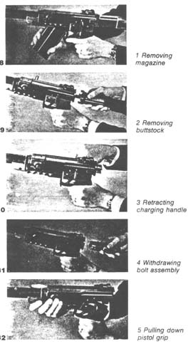 1. Grasp the
pistol grip with your left hand and support magazine with your right hand. Depress
release catch and swing out magazine in a forward direction.
1. Grasp the
pistol grip with your left hand and support magazine with your right hand. Depress
release catch and swing out magazine in a forward direction.
2. Hold the rear section of receiver with your right hand, then activate bolt catch with index finger. Rotate buttstock counterclockwise about one-eigth turn and withdraw stock from receiver. Remove charging handle by pulling it out of guide slot.
3. Draw bolt assembly out of receiver.
4. Depress clip and knock out crossbolt of trigger housing to the right. Pull
down on pistol grip, then lift unit off to the rear. No further disassembly
is necessary for cleaning purposes. Make sure that hammer does not drop after
trigger mechanism has been removed.
5. The SG 510 is reassembled by reversing these steps.
11.
Rifle grenade 58
Weight
2 lb 7 oz
Muzzle vel.
normal charge 131 ft/sec.
booster charge 230 ft/sec.
Max. range
normal charge 186 yards
booster charge 470 yards
The rifle grenade 58 may be fitted with the following warheads:
1. Hollow charge for heavy armour. Modem hollow charge rifle grenades can penetrate
12 to 2 0 inches of "best quality" armour plating.
2.
Antipersonnel with impact detonator.
3. Smoke canister for reducing visibility.
4. Dummy.
All Swiss rifle grenades contain a booster charge. If not required, it is deactivated by forcing a plastic plug down the muzzle, before the grenade is mounted. Hollow charge grenades are fired with a booster charge at all times.
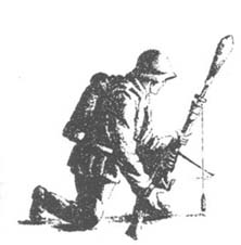
 Figs. 34 and
35 show method of taking aim when target is in view. If the target is not in
view the rifleman uses the scales on the legs of the bipod, together with a
plumb line (33). A second soldier stands behind the first to check side rake.
When launching a grenade, the rifle should on no account be pressed against
one's shoulder. Recoil is particularly fierce!
Figs. 34 and
35 show method of taking aim when target is in view. If the target is not in
view the rifleman uses the scales on the legs of the bipod, together with a
plumb line (33). A second soldier stands behind the first to check side rake.
When launching a grenade, the rifle should on no account be pressed against
one's shoulder. Recoil is particularly fierce!
However, if the rifleman has no hard surface to support the buttstock, he is
recommended to clamp the buttstock under his right arm and hold it there as
best he can, either in a standing or kneeling position.
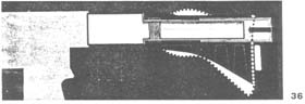
Fig. 3 6 (not shown) shows the dampening mechanism in the buttstock, as well as the deforming zones of the buttstock when it is propped against a hard surface, and pressed into service as a launching pad.
13.
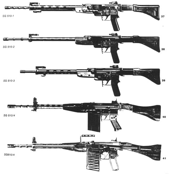
SG 510-1 to SG 510-4 Models for export
 These four commercialized
models (37-40) are basically identical with the S G 510, or, as some people
prefer, StGw 57.
These four commercialized
models (37-40) are basically identical with the S G 510, or, as some people
prefer, StGw 57.
The SG 510-1 being the standard export model, the SG 510-2 a lightweight model, the SG 510-3 a model chambered for the East bloc 7.62 x39 mm(intermediate) cartridge, and the SG 510-4 a model chambered for the NATO 7.62 x 51 mm cartridge. Chile purchased the SG 510 - 4 for her armed forces.
Penetration
ratings for 7.5
Swiss standard round
Distance (yards) 5.5 328 656
Pine boards 24 in. 20 in. 16 in.
Sand 12 in. 16 in. 16 in.
Farmland soil 24 in. 28 in. 24 in.
Packed snow 47 in. 51 in. 51 in,
Steel plating 0.4 in. 0.2 in.


Last Modified on March 15, 1999